The above picture is *NOT* my sprinter. Its great example of how bad black death can get if you cont catch it early.
If you notice your van ticking (more that usual) and an oil smell in the cabin. You probably have black death. Open the hood, pop of the head cover, if it is a black mess, you have it. If not sure, run the engine and you will see smoke puff out from one of the injectors.
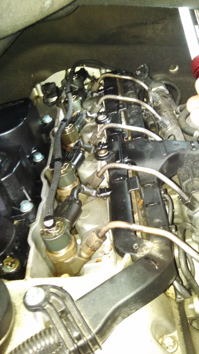
A couple of weeks ago my Sprinter Van was decidely uphappy with my lack of maintenance and decided to start stinkin up the interior. It smelled like burnt oil. I topped up the oil, but the smell did not go away, so I thought I was in for some kind of a gasket replacement. Oops, not today.
Opened up the engine, while running, and there was a Pffft, Pffft sound coming from under the top cover. Little whisps of black smoke, puffing out. I took off the back cover and black death on cyl #3 showed itself…
Here is how to fix it:
- Clean of the black death – de-carbonizer or oven cleaner.
- Engine must be HOT
- One at a time:
- Remove an injector
- Cut a new seat
- Rethread the hole
- New copper washer
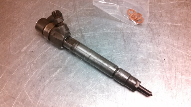
Parts Needed
- OEM Fuel Injector Washers (copper washers)
- OEM 6mm injector clamp bolts
- White ceramic antiseize grease (Loctite LB 8036) – I could not find any of this stuff so I used Permatex Nickel anti seize grease
Special Tools
- Injector puller (maybe… see below)
- Injector seat reamer (DIY if you have a lathe – see below)
- M6x1 long bottom tap (or DIY from a long M6x1 bolt – see below)
- Lots of Carb Cleaner
- Lots of paper towels
Clean It Up
- Remove the injector cover
- Get the engine warm. Warmer the better.
- Using carb cleaner spray all the black crap
- Wait for the carb cleaner to work it magic, it black splooge will get somewhat soft
- Carefully use a screwdriver and work off the splooge, vacuum cleaner helps
- Get a whole bunch of paper towels, shove them down around the injectors and soak out the black crap
- Repeat and repeat…
Looks pretty good now eh?
Loosen It Up
- Re-install the injector connectors and return line (with clips)
- Warm up the engine, get it nice and warm
- Shut the engine off
- While the engine is warm loosen the injector retaining bolt
- Spray carb cleaner in the injector well, around the faulty injector
- Let it sit overnight
- Clean up any remaining carb cleaner
Injector Removal
- Clean up any remainig carb cleaner, by stuffing rags into the injector well
- Run the engine, get it hot
- If you are lucky (like me), the injector will come loose right away. You will notice when running, it will put out a lot more smoke.
- If that does not work, go for a drive, and gas it up a hill – the injector should pop.
- If that does not work get an injector puller from eBay (about $60)
- Shut off engine, disconnect the battery
- Remove the fuel line, return line and the electrical connectors
- Take a 29mm wrench, or a pair of channel pliers and *gently* rotate the injector a little bit. A LITTLE BIT AND BE GENTLE.
- Once it starts to work loose, you can wiggle it and GENTLY pull up on it. The injector will pop out!

Cleanup
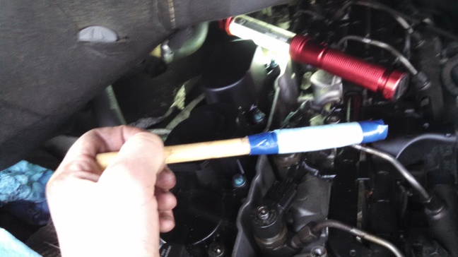
- Spray paper towels with carb cleaner and wipe up as much as you can around the holes
- Use paper towel wrapped around a dowel with carb cleaner to clean inside the hole
- Clean up the injector with carb cleaner
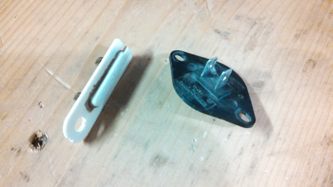
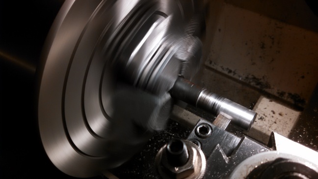
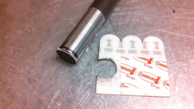
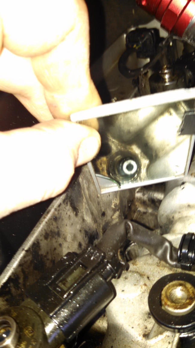
Ream the Seat
Rather than purchase a seat reamer, I turned a piece of steel rod down to 15mm. Then using very strong double-sided tape I put on a nice little piece of 150grit emery paper. Worked real nice.
Clean the Clamp Screw
Cut a slot in the old M6 injector bolt and screw it in-and-out many, many times in the threaded hole to clean it up.
Install Injector
- lube the injector body (not the tip) with anti-seize compound.
- put a little bit of anti seize compound on the copper washer to hold it in place
- place the hold down clamp on the injector and slide the injector into its hole.
- tighten the hold down clamp to 7 N·m (62 lbs. in.) then 90°
- replace the fuel return line, electrical connectors, battery negative lead
- start the motor (might take a bit), let it run and look for leaks. Hopefully it purrs like a kitten.
- put the cover back on
- enjoy.
Reference
Sprinter manual 14-38
Clean out bolt: http://sprinter-source.com/forum/showpost.php?p=171041&postcount=45
DIY Seat cleaning tool: http://sprinter-source.com/forum/showpost.php?p=171043&postcount=46
DIY tools: http://sprinter-source.com/forum/showpost.php?p=171044&postcount=47
Bleed the fuel system: http://sprinter-source.com/forum/showpost.php?p=172658&postcount=61
Injector seal DIY tips: http://sprinter-source.com/forum/showthread.php?t=26341
Injector hold down bolt torque: http://sprinter-source.com/forum/showthread.php?t=25300&highlight=injector+bolts+test
Aqua Puttana tools: http://sprinter-source.com/forum/showpost.php?p=137431&postcount=3
Diesel Injector Puller: http://www.lasertools.co.uk/items/pdf/Products/4762_Instructions.pdf
Remove injector without a tool: http://sprinter-source.com/forum/showthread.php?t=30294
http://sprinter-source.com/forum/showthread.php?t=16068&highlight=black+death
http://sprinter-source.com/forum/showthread.php?p=201523#post201523